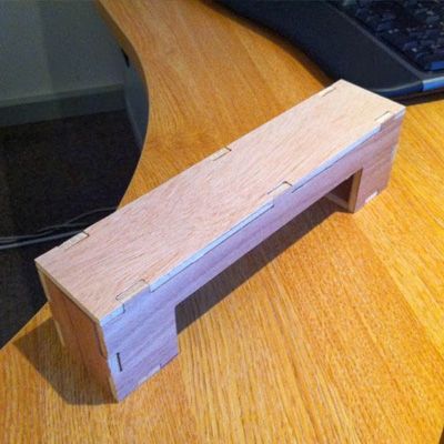
Before the User Group I built a cover for some hot water pipes in my son’s bedroom. My wife had asked me about covering them up and rather than do it the quick, easy and cheap way I figured it would be much more interesting to create a time-consuming, expensive, CNC cut, slot-together frame!
We’ve been a bit busy recently working on the User Group and new software releases to be able to work on much in the Vectric Lab or to blog about what we have been doing. Hopefully we’ll slowly get back to more regular updates between now and Christmas.
One project I had worked on before the User Group was a cover for some hot water pipes in my son’s bedroom. My wife had asked me about covering them up and rather than do it the quick, easy and cheap way I figured it would be much more interesting to create a time-consuming, costly, CNC cut, slot-together frame. Actually I just thought it would be a good learning experience to understand how these types of joints work and also be more likely to look nice and be square if it did not rely on my manual home-improvement skills.
I decided to go with a frame of small ‘U’ shaped boxes that would be cut out of plywood and assembled, then these would be screwed to the wall and larger panels would be attached to them to make the actual cover. First job was to create a prototype to figure out size and allowance so the part would go together without any glue. The first one I cut was out of 12mm plywood; it went together correctly but was a bit loose fitting. This was a useful exercise though as I realised it would be a bit a bit large and heavy in that size of material and also was able to check the shape for fit and size against the pipes. The next one was out of 6mm plywood. This was a better size but still a little loose to hold itself together. So I cut one more using a very small negative offset on the Profile toolpath in VCarve Pro to tighten the joint. This went together perfectly with a little help from the mallet and was a close enough fit to hold itself together. I even managed to stand on it with my full weight just to see how strong it was, it had no problem supporting me, although balancing on it was a bit of a challenge. If you are going to do this type of joint some key points to note are using dog-bone fillets for the corners of the tabs locations (appropriate to the size of the toll you plan to use). Also you need to very accurately measure the thickness of your material to ensure the locations the tabs are going to go into are correctly sized.
Once I was happy with the concept of the box working I did a quick sketch to figure out how many box sections I wanted to support the panels and to make a few notes. From there I went into VCarve Pro and made copies of all the components to make 7 of the boxes and also drew the vectors for the side and front panels as well as some stiffening parts in case they were required for the inside of the frame to join the box joints.
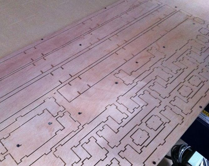
Once I had all the parts laid out I calculated the toolpaths for all the profiles and drill holes for attaching it to the wall. I made sure that everything had tabs on it to hold the parts in place as they were machined. I also created a toolpath to run first to create location points for me to screw the material down on the sacrifice sheet on the CNC. I made sure these hold down screws were away from the cuts but close enough to stop the material lifting as it was cut.
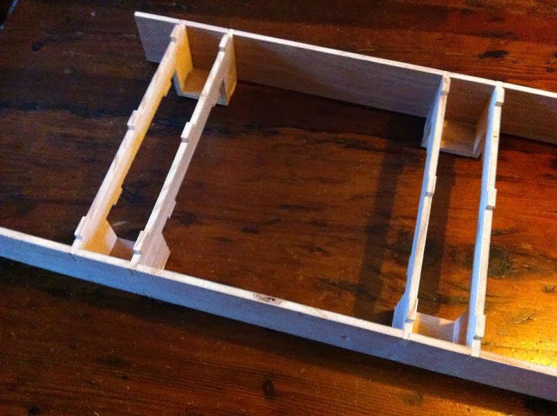
All the box sections and side panels were cut out of one sheet of 2’ x 4’ plywood. Once this was cut I removed all the pieces, gave them a quick sand and took them home for a test assembly. Everything went together really nicely but I realised at the point where the top and bottom sections joined together it would probably not have enough support to hold it straight. So I decided I would go ahead and cut the internal stiffening pieces when I cut the main cover panels the next day. These parts were cut out of another piece of plywood and at this point I was ready for installation.
Attaching the frame to the wall was straightforward; I deliberately designed it so you could get to the holes for the screws. I put the frame in position against the wall and drilled pilot holes for each location. I removed the frame then and drilled the holes and pushed in plastic wall anchors. Then the frame went back into position and was quickly screwed to the wall. At this point all that was left was to attach the main panels to the top and bottom. These fitted and went on just as easily as everything else, with just a gentle encouragement from the mallet. The interior had the look of an old wooden frame aircraft when it was done, Brian suggested I use clear plastic covers for the front so you could see inside; my wife quickly vetoed that suggestion…
Although this is obviously total overkill for the particular task it was a fantastic learning experience and I really got to appreciate just how accurately parts can be made on a CNC. In total the whole assembly was 40 separate pieces, all of which went together without a problem and made a very sturdy structure when complete. No glue, nails or screws other than the ones holding it to the wall!
I would like to end by thanking Mr. 2D himself, Bill Young for inspiring me to delve into world of flat things. I will definitely be using some of these ideas in upcoming projects.

Vectric Ltd
Precision House
2 Arden Road
Alcester
B49 6HN
Registered in England Number 05382596
VAT Registration GB115123072
Privacy Policy |
Cookie Policy |
Terms and Conditions



