We have a lot of musicians here at Vectric, which is why we’re always fascinated and a little in awe when one of our makers makes an instrument, and in this case in particular, a guitar. Being such complex projects usually combining different woods for different parts all the way down to the electrics and pickups that get installed we’re always curious to understand how our makers approach such an interesting and complicated project.
This month, we spoke to Eckart Grote, one of our forum members and makers from Germany, who made his own bass guitar as he was in search of a particular guitar sound inspired by one of his favorite musicians.
Vectric: Hi Eckart, Thanks for speaking to us. Let’s start by you telling us about your setup. What machine do you use and what version of the software do you have?
Eckart: Hello! I have a BZT PFE1000-PX and the control kit from Sorotec with Mach3 software and I have Aspire 11.0, 10.5 and 9.5.
Vectric: So, tell us a bit about yourself. What’s your background and how did you discover CNC?
Eckart: I am a trained aircraft mechanic and had a year of metal basics including milling, turning, welding, riveting, drilling, filing and driving (hammering aluminum into molds). Through friends, acquaintances and model making, I came into contact with CNC technology. In the airline where I worked in line maintenance, there is a model assembly which has a CNC machine and I was able to gain my first experience there. However, I couldn't really get used to the software used there.
Due to too little utilization (a drop in workload) in my profession, I have become self-employed part-time and bought my own CNC machine to earn a little extra money with CNC milling. I mainly wanted to make shadow boards (the boards mounted to the wall which have the outlines of tools that are stored on them) that are used in aviation, so that no tools are left on the plane during repair or manufacture. I then also began to offer these for other industries.
Since Aspire can generate vectors from bitmaps and the path from the drawing to the finished product is very easy, I began to use Aspire. Currently I make many serial products from walnut, oak and olive wood.
Vectric: A bass guitar is a pretty complex build, what was it that inspired you to do this as a project?
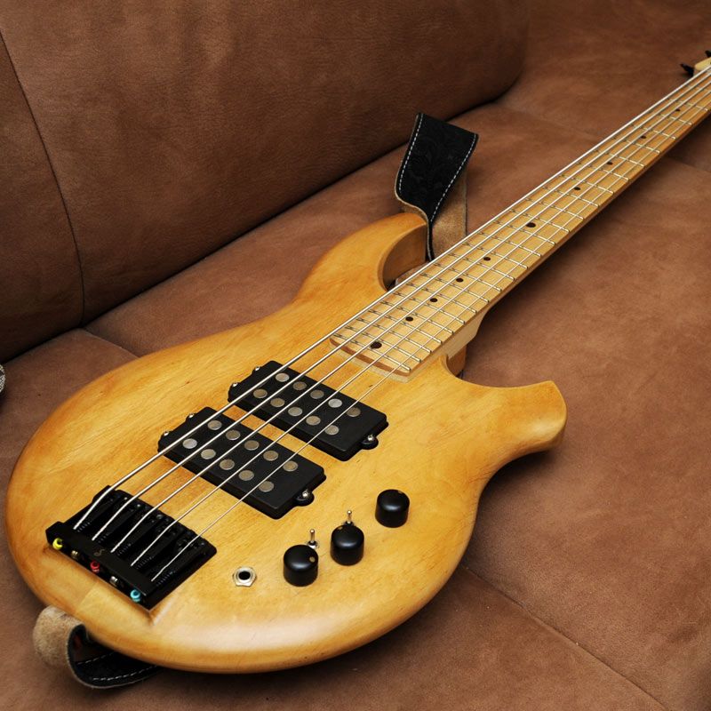
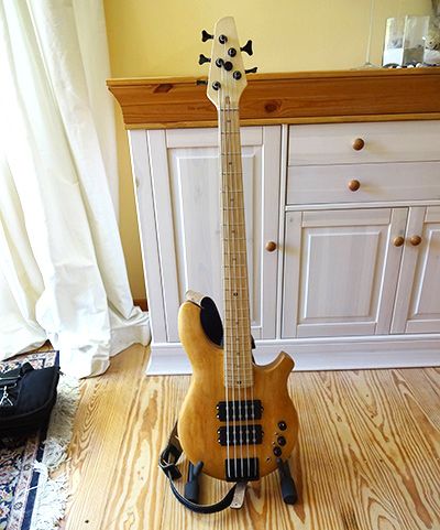
Eckart: I play in a band that also has a few pieces in Drop - D and a 4-sided bass guitar only goes down to E normally. So I tried a few 5 string bass guitars and wasn’t quite satisfied with the string spacing, so I thought why not do it yourself and try something. I wanted the sound and design of the guitar to be similar to an Ernie Ball Music Man Bongo, but not be a complete copy and reflect my own taste.
I wanted the 3D elements on both sides of the body and didn’t want the bass to be too heavy (I’m not getting any younger!) I had previously looked at a few projects by Alex Navarro, rebuilding the jazz bass in a slightly different way and had already made a few handmade basses.
Vectric: Ahh Alex Navarro… another Vectric user! What wood/material did you use for this project? Did you have to treat or prepare it in any way and where did you source your materials from?
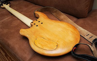
Eckart: The body consists of 2 alder boards, which were glued together and then dressed with the CNC milling machine.
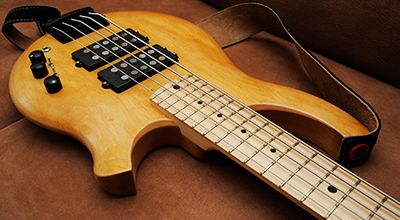
The neck and the fretboard are made of maple, in which 2 carbon rods are installed in addition to the neck rod (Trussrod). The neck was also dressed with the CNC machine. I got the fretboard planed to thickness from BassParts.de. I bought the wood for the body and neck from the wood dealer Cropp in Hamburg-Harburg. The hardware comes from Rockinger Guitars, Thomann and the pickups are from Haeussel.
Vectric: Guide us through your design process. Did you sketch your design first? What tools/features in the software helped you design your project?
Eckart:I constructed the bass without sketches in Aspire. A bitmap of the Bongo bass was used for drawing as an orientation (of the basic shape) because I knew that the bass should have a rather round circular shape. I then tried different body variants until I liked one. The neck and the bridge were taken with a scale of 864mm as the basis for the construction with of the drawn sides.
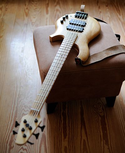
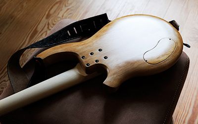
Since I wanted to have the body to have 3D elements on both side, I tried different options and went with the easiest. The one-way curve was applied to the outer edges of the body with a flare on the horns, then center filled and trimmed with the contour. The 3D construction is 22mm high and is on a 22mm high base plate. I took the same construction for the back. The body is thus 44mm high.
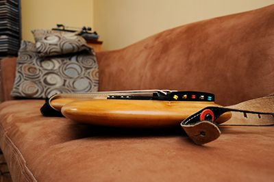
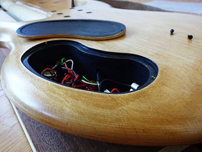
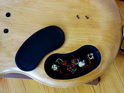
In order to make the design on the horns a bit more pleasing, I added outgoing and incoming phases, which I have achieved by moving a contour toolpath using a V-cutter with a fixed depth. Since the bridge is close to the edge, a block had to be made to compensate for the curves there. The electrical compartment including lid was cut out of the 3D model of the body and was also milled in 3D.
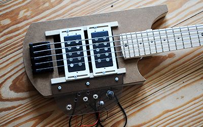
For the pickup position, an MDF body with movable pickups was produced for testing. Just so you know, an MDF guitar doesn't sound so bad!) The electronics were then screwed onto a plastic plate on the MDF body to test the switching options. After that, I was able to determine switches, pots and pickup placement and measurements.
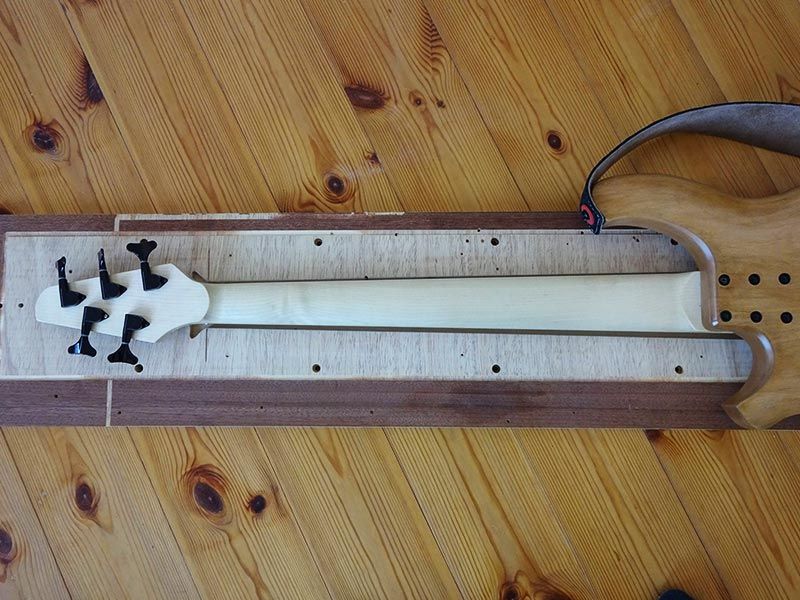
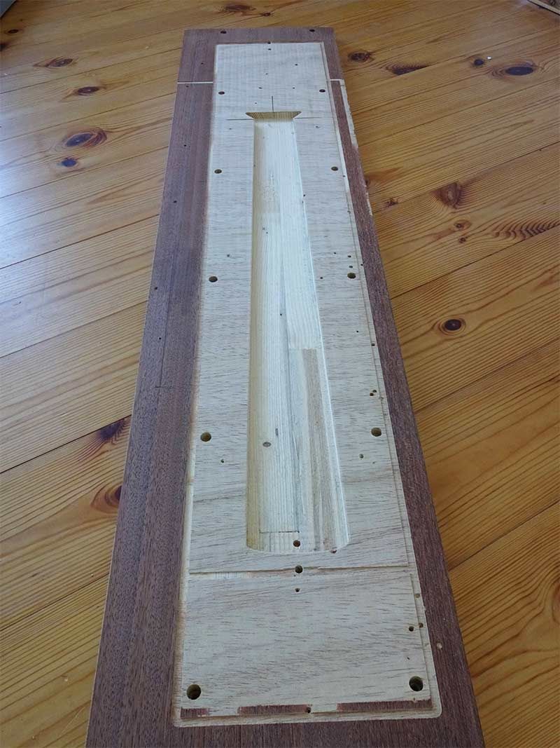
For the neck and the fretboard I used the control path tool for the 3D basic shapes. The neck head and body transition was a bit difficult and eventually I came up with a simple idea. A base plate that has 26mm in the head and body area and almost 0mm in the neck area with round transitions. This was done with the two rail sweep tool. I added the basic shape of the neck onto it and then cut it into component layers with the 3D slicing tool and kept only the one under layer.
Vectric: What toolpath strategies did you use for this project and why did you use them? Can you elaborate on the tools you used? Feeds and speeds?
Eckart: I have used many 3D roughing and finishing toolpaths, as well as contour, pocket and drilling tool paths. The roughing and finishing toolpaths are created by selected vectors.
First, the boards of the body are dressed laterally on the glue connection (contour toolpath) and after gluing together are dressed to thickness (angle pocket toolpath). Depending on the condition of the boards, I use 6mm, 8mm, 12mm and 20mm end mills with preferably straight cutting edges for dressing the boards. The body is stretched on vacuum pads with rubber lips for dressing, as these can compensate for irregularities and can also clamp crooked wood.
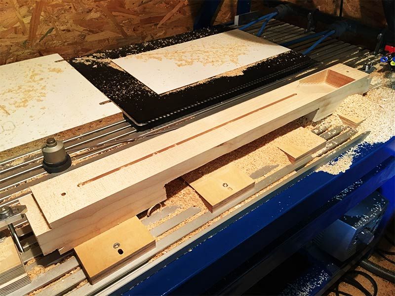
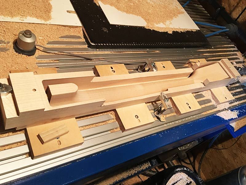
The neck is stretched on wooden blocks, which are screwed to a fixed position on the T-slot table and dressed with a 20mm end mill. Then the pockets for the truss rod and the alignment holes for turning the neck and gluing the fretboard are milled with the appropriate cutters. After inserting the carbon rods and the truss rod, the fingerboard is glued on. Then I roughed the head with a 6mm end mill 3D and finished it with the fretboard. The fret markings, the groove for the saddle and the pockets for the machine heads are milled followed by the slots for the frets, using a 0.6 mm end mill.
The feed for the 0.6mm cutter is 1/2 cutter diameter to avoid any clogging of the cutter. The router follows the 3D model of the fretboard. After that, I turned the neck around to mill the back. Here I took 6mm end mill for roughing (Z-plane one after the other in the Y-direction) and 6mm ball cutter for finishing (raster 33°) and at the end, the contour is milled with the 6mm end mill.
I then used the same 6mm mill, the body was roughened (Z-plane one after the other in the X direction), the electronics compartment, (which is also designed in 3D), as well as the pickups, neck recording pocket and the alignment holes. For finishing (contour mode) I used a 12.7mm ball nose cutter, because the bridge body transition is then more homogeneous and this was only achieved by choosing the milling cutter.
A 12.7 mm 90° V-bit router was used for the body phases. 3.175mm and 2mm routers were used for switch and screw holes, as well as for milling out the neck bolt-on. Finally, the contour was milled again with a 6mm end mill. The electronic compartment cover has been roughed and finished from 2 sides in 3D with a 6mm end mill.
I adjusted the feeds and speeds of the tools to a chip size of 0.05-0.066mm depending on the wood. The milling depth for end mills can be up to the diameter of the router provided the spindle can handle it. For plunging, I take half of the feed if no plunging ramp is taken. I use Conventional milling for the toolpaths when working with wood.
The 6mm end mill (Sorotec) with 2 cutting edges is my standard milling cutter. Depending on the task, I use straight and spiral milling cutters.
The cutters and settings used:
6mm end mill (18000 rpm, 2400mm/min, with 24000 rpm to 3200mm/min)
6mm ball nose cutter with 2 blades (24000 rpm, up to 4200mm/min with 2.3mm feed)
12.7mm ball nose cutter from CMT with 2 cutting edges for finishing (12000 rpm 1250mm/min)
12.7mm 90° V-Bit from CMT (18000 rpm, 1800mm/min)
3.175mm end mill (18000 rpm, 2000mm/min)
2mm end mill from Sorotec (18000 rpm, 2400mm/min for the corners of the neck attachment)
0.6mm end mill with 0.3mm lining for the fretboard slots (30000rpm, 2400mm/min)
12-20mm end mill from CMT for dressing with straight cutting edges with small feed 1-2mm.
Vectric: Wow, thanks for such an intricate explanation! As we said, a guitar project is such a complex build, that this really highlights the level of detail that you need to consider before starting a project like this. So, how did you complete your project? E.B. Sanding, painting, pickling, etc. What tools did you use to finish your product? What products have you used?
Eckart: Normally I always use shellac for guitars, but I didn't like that for the body, because the wood is a bit too soft and the lacquer had too much shine. So I wiped the shellac off with spirit and then painted it with Clou Nitrolack Spray. This has a velvety sheen, dries quickly and is quite hardwearing. I used a spray can to apply the paint as it is easy and gives an even finish however you will need to wear respiratory protection such as a mask to apply this varnish.
For the neck and the fretboard I have used shellac again as a finish, because maple has enough hardness of its own and the shellac gives a good natural grip feeling. The shellac is diluted with alcohol and wrapped in a linen cloth with soaked cotton wool and polished. The electronic compartment and the pickup millings are coated with graphite lacquer for shielding.
Vectric: What would you say worked well on this project and what would you do differently next time?
Eckart: The construction of the neck with the 2 track bow tool for the fretboard and the basic shape of the neck and the use of base plates as a level for transitions from the headstock to the neck and from the neck to the body attachment. The new features of slicing 3D models in Aspire 11 will make it easier to approach this kind of project next time.
For the next project like this, I would use the note function more for work steps and solutions, because I work according to the principle of "learning by doing" and I usually try out many solutions and then will be able to record which solution works best. I also need to work out better reference points on my vacuum table for machining the body from both sides.
Vectric: Do you have any tips to share with us and the Vectric community?
Eckart: Having a ready-drawn 3D model is all well and good, but sometimes selecting the right toolpath option and tool is faster and easier to produce the desired model. The radius of the fretboard, planed to thickness and glued on, is milled to oversize in width, so that an edge remains around the neck, which is used to stretch out the back.
In certain areas, 3D finishing is also possible with an end mill and little grinding effort, in order to avoid frequent tool changes. For example, the fretboard and the electronics compartment cover only have a slight curvature. For the fretboard I milled a sanding block with a negative shape of the fretboard. This can also be used later to trim the frets.
I usually mill the contour last and leave 1-3/10 mm, then I don’t need any tabs. For the neck I used a tab at each end. I use various clamping methods with fixed reference points on my T-slot plate, often marked with holes. These reference holes are available in the Mach3 table. To check the reference holes, I use e.g. a demolished milling cutter, where the tip is ground off.
To check the reference points, the spindle now moves to the X and Y coordinates of the reference point without Z movement. With the Z-axis, the spindle with the keyboard is briefly brought over the hole and the ex-milling cutter is pushed by hand into the hole, if it fits, everything is fine. The e-milling cutter is tightened only with a little friction at the spindle, so that movement is only possible in z-axis direction by hand.
I used this method for the body which is clamped on the vacuum table to ensure the correct reference point as the vacuum table has a hole every 10mm and the reference pin had some room to play with. The spindle is of course switched off during this process. I have a fixed location for the length sensor since most of the time I mill with the machine bed as the Z reference.
Vectric: And Finally Eckart, we’d like to thank you for your time and for explaining to us the intricacies of such a great project. What projects do you have planned for the future and do you have a website/ social media where our community can find you?
Eckart: You’re very welcome! I would like to make a bass with a continuous neck and this 5 string as 4 string bass. I have a Les Paul guitar that is already in the works, plus an underwater housing for an exposure meter. There’s also a ceiling lamp, a model airplane, and some laser projects. I don’t use social media but my website is www.ich-fräs-das.de
Vectric Ltd
Precision House
2 Arden Road
Alcester
B49 6HN
Registered in England Number 05382596
VAT Registration GB115123072
Privacy Policy |
Cookie Policy |
Terms and Conditions


